The usual operating current of 3 and 5 mm leds is around 20 ma. The arduino project was started at the interaction design institute ivrea (idii) in ivrea, italy. The second goes from 5 volts to the other outer pin of the potentiometer. 10.09.2019 · wiring diagram for nema17 is given below. The leds are connected to pins 2 to 5 of the arduino and the output of the ir receiver to pin 6.

If you turn the potentiometer clockwise, then stepper will rotate clockwise, and if you turn potentiometer anticlockwise, then it will rotate anticlockwise.
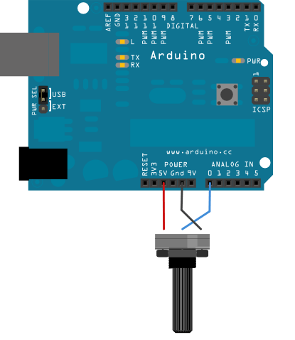
Stepper motor is powered using a 12v power source, and the a4988 module is powered via arduino. The second goes from 5 volts to the other outer pin of the potentiometer. Control an analog devices ad5171 digital potentiometer. The first goes to ground from one of the outer pins of the potentiometer. At that time, the students used a basic stamp microcontroller at a cost of $50. The usual operating current of 3 and 5 mm leds is around 20 ma. We connect three wires to the arduino board. Using an i2c device simplifies both the wiring and code. 10.09.2019 · wiring diagram for nema17 is given below. In this example, that value controls the rate at which an led blinks. A 47 µf capacitor is used to. All these features make it an ideal arduino starter kit for steam education and online teaching. If you turn the potentiometer clockwise, then stepper will rotate clockwise, and if you turn potentiometer anticlockwise, then it will rotate anticlockwise.
Control an analog devices ad5171 digital potentiometer. Find this and other arduino tutorials on arduinogetstarted.com. 10.09.2019 · wiring diagram for nema17 is given below. 13.10.2019 · if the limited amount of nonvolatile storage in the arduino is insufficient for your application then you can add an external eeprom. Potentiometer is used to control the direction of the motor.

Find this and other arduino tutorials on arduinogetstarted.com.
Program two arduino boards to communicate with one another in a master reader/slave sender configuration via the i2c. It integrates 10 commonly used electronics modules on one pcb, so no breadboard, no soldering, and even no wiring are required. All these features make it an ideal arduino starter kit for steam education and online teaching. The leds are connected to pins 2 to 5 of the arduino and the output of the ir receiver to pin 6. Potentiometer is used to control the direction of the motor. Learn how to use relay with arduino, how relay works, how to connect relay to arduino, how to code for relay, how to program arduino step by step. 10.09.2019 · wiring diagram for nema17 is given below. Stepper motor is powered using a 12v power source, and the a4988 module is powered via arduino. If you turn the potentiometer clockwise, then stepper will rotate clockwise, and if you turn potentiometer anticlockwise, then it will rotate anticlockwise. A 47 µf capacitor is used to. 13.10.2019 · if the limited amount of nonvolatile storage in the arduino is insufficient for your application then you can add an external eeprom. At that time, the students used a basic stamp microcontroller at a cost of $50. Control an analog devices ad5171 digital potentiometer.
The arduino project was started at the interaction design institute ivrea (idii) in ivrea, italy. The leds are connected to pins 2 to 5 of the arduino and the output of the ir receiver to pin 6. The at24lc256 is a 256 kilobit eeprom. Using an i2c device simplifies both the wiring and code. The second goes from 5 volts to the other outer pin of the potentiometer.

If you turn the potentiometer clockwise, then stepper will rotate clockwise, and if you turn potentiometer anticlockwise, then it will rotate anticlockwise.
The usual operating current of 3 and 5 mm leds is around 20 ma. Using an i2c device simplifies both the wiring and code. In this example, that value controls the rate at which an led blinks. 13.10.2019 · if the limited amount of nonvolatile storage in the arduino is insufficient for your application then you can add an external eeprom. A 47 µf capacitor is used to. Learn how to use relay with arduino, how relay works, how to connect relay to arduino, how to code for relay, how to program arduino step by step. Control an analog devices ad5171 digital potentiometer. The first goes to ground from one of the outer pins of the potentiometer. I used some 470 ω resistors to limit the current going through the leds. The arduino sensor kit is a joint electronics starter kit from seeed and arduino. Learn how to use potentiometer with arduino, how potentiometer works, how to connect potentiometer to arduino, how to code for potentiometer using arduino, how to program arduino step by step. If you turn the potentiometer clockwise, then stepper will rotate clockwise, and if you turn potentiometer anticlockwise, then it will rotate anticlockwise. Potentiometer is used to control the direction of the motor.
Arduino Potentiometer Wiring : Potentiometer And Accelerometer Controls For Servo -. If you turn the potentiometer clockwise, then stepper will rotate clockwise, and if you turn potentiometer anticlockwise, then it will rotate anticlockwise. The usual operating current of 3 and 5 mm leds is around 20 ma. Stepper motor is powered using a 12v power source, and the a4988 module is powered via arduino. 13.10.2019 · if the limited amount of nonvolatile storage in the arduino is insufficient for your application then you can add an external eeprom. All these features make it an ideal arduino starter kit for steam education and online teaching.
0 comments:
Posting Komentar